The propagation characteristics of electromagnetic waves often exhibit strong selectivity depending on the medium. This is particularly evident in quartz optical fibers. Despite the extremely broad electromagnetic spectrum, ranging from microwaves to gamma rays, the optical band where fiber optic communication can operate effectively is confined to a very narrow range within the near-infrared region. As shown in the figure below, this specific low-loss region constitutes the fiber optic “transmission window.”
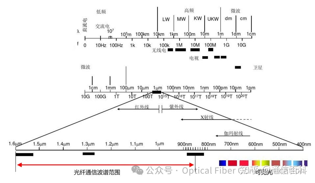
The spectral range indicated by the red arrow is primarily determined by the intrinsic absorption properties of quartz material (ultraviolet electronic absorption, infrared vibrational absorption) combined with Rayleigh scattering losses.
Understanding Loss Mechanisms: Photon Energy & Wavelength Relationship
To understand loss mechanisms, the relationship between photon energy (E) and its wavelength (λ) must be clarified. Photons, as quanta of energy, have energy proportional to the electromagnetic wave’s frequency (ν):
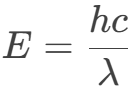
- E: Photon energy (Units: Joules J or electronvolts eV)
- h: Planck’s constant
- c: Speed of light in vacuum (3×10⁸ m/s)
- λ: Photon wavelength (Units: meters m)
Physical Essence: As quanta of energy, a photon’s energy is proportional to the electromagnetic wave’s frequency ν (E = hν). Since wavelength and frequency are related by c = λν, energy is inversely proportional to wavelength.
The attenuation mechanisms of light in quartz glass (the core material of optical fibers) stem mainly from three physical effects:
- Electronic Absorption: When photon energy > 9 eV (wavelength < 138 nm), photons can excite valence band electrons to jump to the conduction band, causing strong optical absorption. For example, near 200 nm wavelength, losses can be as high as thousands of dB/km or more. Since fiber optic communication wavelengths are far longer than this, the impact of this mechanism is negligible.
- Molecular Vibration Absorption: Occurs when photon energy matches molecular bond vibrational energy levels. For instance, strong resonance of the OH bond at 1383 nm (like a particularly high speed bump) leads to a strong hydroxyl absorption peak.
- Multi-phonon Absorption: For wavelengths greater than 1600 nm, Si-O bond vibrations dissipate energy (like a series of continuous speed bumps on a road), leading to multi-phonon absorption.
An Analogy: Fiber as a Highway, Light as Trucks
How to understand the three points above intuitively? Let’s imagine the optical fiber as a highway, and light as trucks driving on it.
- Level 1: Super High Wall (Deep UV Absorption)
- Location: Before 138 nm (10x shorter than violet light)
- Principle: A 9-meter-high brick wall (corresponding to 9 eV energy)
- Truck Encounter: Only supercars (deep UV light) can crash through the wall, but get destroyed (light energy completely absorbed).
- Real Impact: Light used in everyday communication never reaches here, so it’s irrelevant.
- Level 2: Continuous Speed Bumps (Infrared Vibration Absorption)
- Location: Beyond 1600 nm (2x longer than red light)
- Principle: Dense rubber speed bumps (corresponding to molecular bond vibrations)
- Truck Encounter:
- At 1383 nm: An especially high speed bump (hydroxyl absorption peak).
- 1600 nm: Increasingly dense speed bumps (multi-phonon absorption).
- Real Strategy: Either avoid this area or eliminate the bumps.
- Level 3: Random Dense Fog (Scattering Loss)
- Fog Location: Present along the entire road, denser in short-wavelength regions.
- Fog Principle:
- 400-1600 nm range: Thin fog (Rayleigh scattering), densest in blue region (∝ 1/λ⁴).
- Defect Sections: Local sandstorms (Mie scattering, rare in modern fibers).
- Truck Encounter: Light rays, like trucks, deviate from their lane, gradually losing energy.
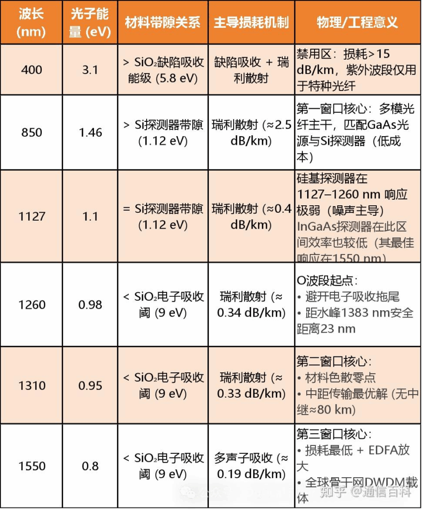
Combining the key data mentioned above, we summarize it in the table below:
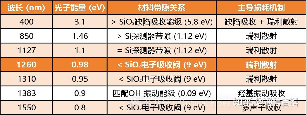
It must be emphasized that a fiber optic communication system is an integrated whole. The selection of the transmission window depends not only on the loss characteristics of the fiber itself but also must match the emission wavelength of the light source and the response wavelength range of the detector.
Therefore, in the table above, I have added two key points: 850 nm and 1127 nm. These additions are primarily based on considerations for source/detector matching.
This leads us to the following classic diagram:
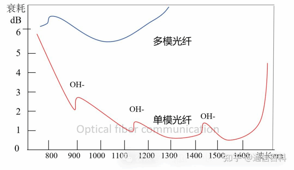
In the early 1970s, breakthroughs in fiber material purification technology (especially reducing hydroxyl content) brought the loss in the short-wavelength band (800–900 nm) below 20 dB/km for the first time. This band, being the first to achieve practical application, was established as the “First Window“, primarily used in multimode fiber systems.
At that time, the most technologically mature and economically practical light source was the Gallium Arsenide (GaAs) Light Emitting Diode (LED). GaAs, as a direct bandgap semiconductor, has a room-temperature bandgap energy of approximately 1.42–1.43 eV. Using the approximate relationship between semiconductor bandgap and emission wavelength, the cutoff wavelength formula is:
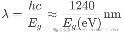
Substituting Eg = 1.43 eV yields λ ≈ 867 nm, close to the 850 nm band. Note: The light around 850 nm here isn’t even laser light; it’s just ordinary LED light.
I have seen in some articles that the first window was designed specifically to cooperate with LEDs. I don’t entirely agree. My perspective is:
System Compromise: Large-core multimode fiber was inherently a sacrifice made to match the large emission area and wide divergence angle of LEDs. Otherwise, coupling optical power would have been impossible.
Physical Constraint: The bandgap of GaAs material dictates that LEDs can only emit light around 850 nm; this is a law of nature. GaAs, as the only commercially viable visible/near-infrared LED material (in the 1970s), has an intrinsic bandgap (1.42 eV). Quantum mechanics constrains its emission wavelength to around 850 nm (Calculation: λ=1240/1.42≈870 nm). This is a natural law; humans cannot change it.
Material Engineering: Although early quartz fiber loss at 850 nm was not the absolute minimum (≈ 4 dB/km), it was 10 times lower than the loss at 650 nm (red light). It was the only viable option. Using 1300 nm (theoretically lower loss) was impossible as there were no commercial infrared LEDs available then, and InGaAs detectors cost 10 times more than Si PD detectors.
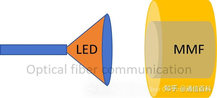
LEDs have a large emission area and wide divergence angle. Therefore, they require matching with large-core multimode fibers (corresponding to a large Mode Field Diameter – MFD) to efficiently collect and transmit their emitted optical power.
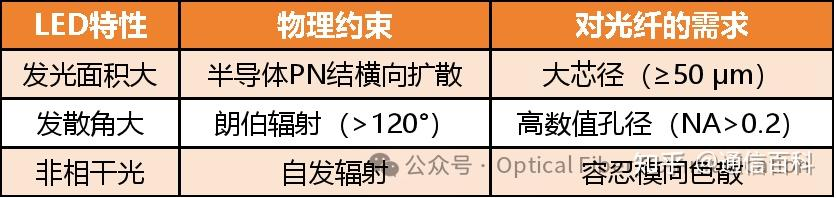
In summary, the logic is represented in the diagram below:
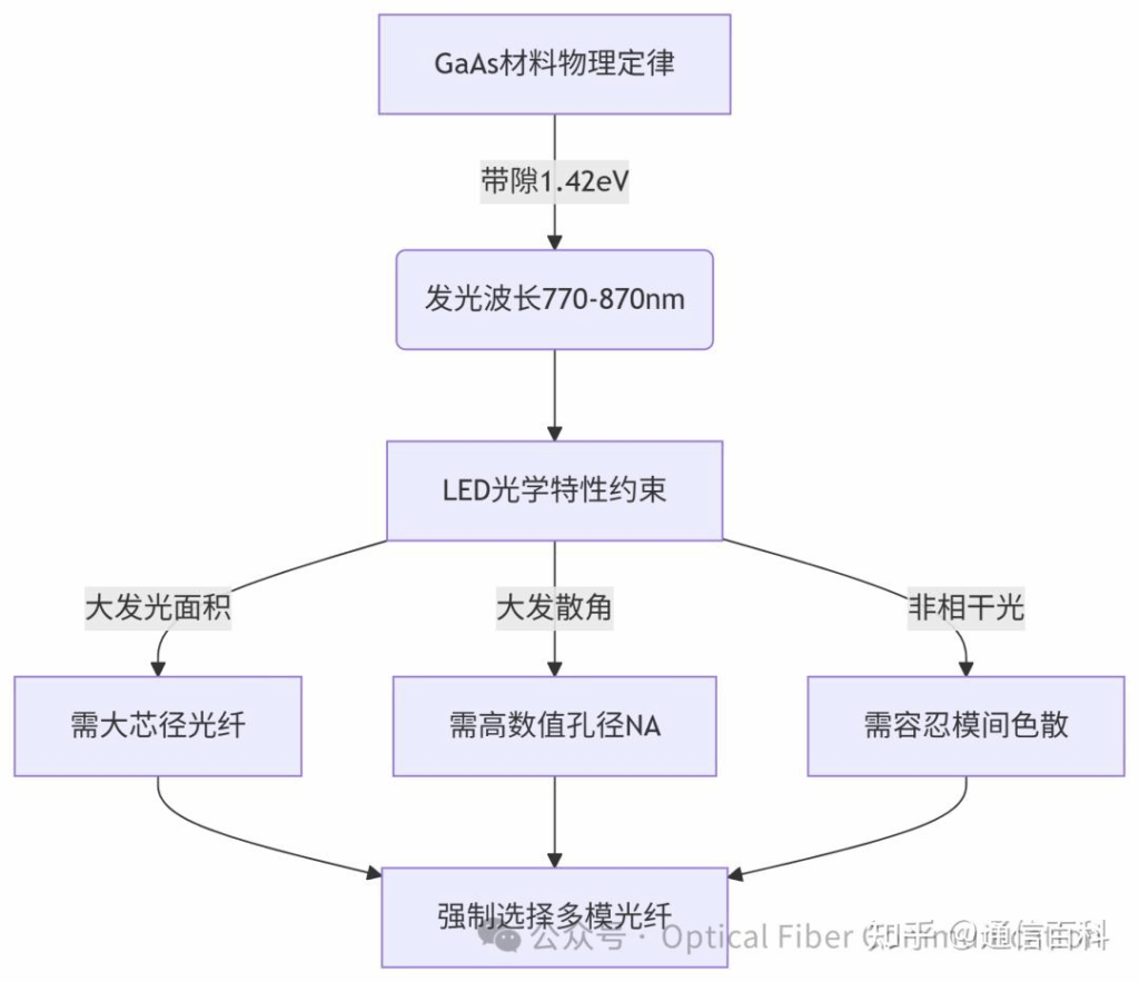
Note: Popular explanations for terms in this diagram like Numerical Aperture and Modal Dispersion will be covered in a subsequent article.
Legacy & Continued Relevance of 850 nm
Even today, dominated by lasers, 850 nm + Multimode Fiber remains the core solution for short distances, inheriting two key genes from the LED era:
Cost Structure: Multimode fiber system cost is 1/4 that of single-mode (2023 LightCounting data).
VCSEL Lasers: Continue the GaAs material system, still achieving highest efficiency at 850 nm.
1127 nm and 1260 nm: The Silicon Detector Factor
Continuing, we come to 1127 nm and 1260 nm. One might ask: Why do these wavelengths suddenly appear?
First, let’s explain where 1127 nm comes from. This brings us to the bandgap of Silicon (Si) photodetectors (not the bandgap of SiO₂ fiber). Silicon has a bandgap energy of 1.12 eV at room temperature, which is the theoretical cutoff point for intrinsic absorption in silicon. Using the same cutoff wavelength formula:
λc≈1107 nm
Note: In engineering, an approximate value of Eg ≈ 1.1 eV is often used, yielding λc ≈ 1127 nm. This value can be thought of as the “security gate” of the silicon chip fab (detector characteristic), unrelated to the fiber highway.
Urbach Tail & the Shift to 1260 nm
Although silicon’s engineering cutoff wavelength is 1127 nm, the Urbach tail causes severe problems in the 1127–1260 nm range. This means photons with wavelengths longer than 1127 nm have insufficient energy to excite electrons across silicon’s bandgap; detector responsivity should theoretically drop to zero.
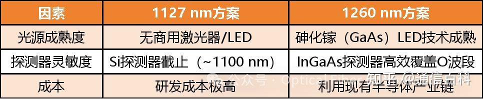
As mentioned earlier, the fiber optic transmission window needs to consider both fiber loss and source/detector performance. Therefore, to avoid the detrimental effects of the detector’s electronic absorption tail on the short-wavelength side, the engineering community shifted the starting point of the communication O-band window from the theoretical minimum of 1127 nm to 1260 nm.
Finally, this section is summarized in the table below:
Based on the above, we have the First Window at 850 nm (used with multimode fiber), the Second Window at 1310 nm (used with single-mode fiber), and the Third Window at 1550 nm (used with single-mode fiber). These are the most traditional and commonly used windows.
Furthermore, the ITU-T subdivides the fiber optic communication bands into six segments: O, E, S, C, L, U, covering a broader range.
E-band: 1360-1460 nm, often called the Fifth Window.
O-band: 1260-1360 nm, corresponds to the Second Window.
C-band: 1530-1565 nm, corresponds to the Third Window.
L-band: 1565-1625 nm, often called the Fourth Window.
发表回复